



Best-fit alignment vs RPS alignment: choosing the right strategy in your CMM inspection
As we all know, in any CMM or 3D scanning workflow, alignment is the step that decides how the measured parts talk to CAD and to the spec drawing. All results and decisions that follow are only as good as the reference system you choose. Among the most widely used strategies, we have best-fit alignment and RPS (Reference Point System) alignment. Understanding the difference between them is essential for reliable inspection.
What is a best-fit alignment?
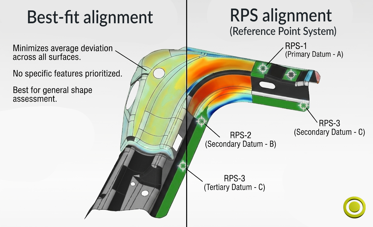
A best-fit alignment is a mathematical coordinate transformation between measured data and the nominal geometry of the part that minimizes the overall deviation between them. Essentially, the CMM software translates and rotates the point cloud or feature set so that selected points match the CAD model as closely as possible, often using a least-squares algorithm.
Given that it distributes the error across all the chosen points, best-fit is particularly useful and used for cast parts, freeform surfaces, complex shapes, and components without a clear datum scheme. It is frequently applied in process development, reverse engineering, or form analysis, where the aim is to understand how the entire part behaves to nominal, rather than to verify strict datum-based requirements.
What is a RPS aligmment?
Instead, the Reference Point System alignment (RPS) uses a set of defined reference points on the part to constrain all six degrees of freedom, making the virtual setup reflect the real fixture or assembly condition. Each reference point can constrain motion along one or more axes; together, the points establish a clear and repeatable coordinate system analogous to the datum target scheme.

RPS is associated with automotive and transportation applications, particularly sheet-metal body parts, closures, and subassemblies.
So, basically… what’s the difference?
Let’s make it simple:
- Best-fit alignment lets the CMM software “average” all selected points to minimize the overall deviation between the part and CAD;
- RPS alignment locks the coordinate system to a small set of defined reference points that mimic how the part is located in the real assembly
In practice: when to prefer best-fit?
We have seen characteristics and distinctions between best-fit and RPS. Now, let’s determine when one alignment type is preferable based on the type of work.
Best-fit alignment is a good starting point when global geometry and process trends are more important than strict conformance to a datum reference frame. For example:
- Early production castings or freeform components, where designers and process engineers want to understand systematic shifts, warpage, and shape trends
- Parts with incomplete, unreliable, or absent datum definitions on the drawing, where a functional coordinate system shall be defined from available geometry
In these cases, best-fit tends to give a stable snapshot of the part’s behavior, which is valuable for process optimization and design feedback.
When to prefer RPS alignment?
RPS alignment is the better choice when the inspection must replicate a functional locating condition or a specified reference point scheme from the drawing or processing documentation. Typical situations include:
- Automotive sheet metal parts and body components, where RPS defines how panels are in the body shop and in virtual body-in-white assemblies
- Subassembly and virtual assembly analyses, where each part must be aligned consistently before simulating joining conditions and evaluating gaps and flushness
- Any case where customers, standards, or internal procedures call for specific locator points or datum targets as the legal reference for conformity decisions
Because the same points are reused from part to part, RPS alignment offers high repeatability and traceability for series production.
Risk and limitations of each method
Every alignment choice involves trade-offs. A best-fit can mask local datum or feature violations by averaging deviations across many surfaces. A part that is clearly out of tolerance in a datum-based frame can look “better” under the best-fit because the error is distributed to minimize the overall distance to CAD.
On the other hand, a rigid RPS scheme can be very sensitive to individual reference points: if one locator area is damaged, unstable, or poorly manufactured, it can drive large apparent deviations in the rest of the part. This can make good local geometry look much worse simply because the coordinate system is tied to a problem point.
For this reason, metrology teams often apply more than one alignment to the same measurement data, for example, combining a datum or RPS-based alignment for compliance checks with a best-fit alignment for process and form analysis.
Practical decision guidance
As we previously said in the alignment best practices, the drawing and GD&T should always be the starting point. If the part has a defined datum reference frame or a specified RPS table, that reference should govern conformity evaluation and reporting. When the drawing does not communicate, or when the inspection goal is more diagnostic than contractual, best-fit (carefully applied to meaningful areas) can provide valuable insight into how the manufactured part actually behaves.
To summarize:
- Use RPS or datum-based alignment when you need traceability and comparability to specifications
- Use best-if when you want to understand global geometry, trends, or root causes
Applying both in a controlled way gives a more complete picture and makes alignment a powerful tool rather than a hidden source of variation!