

Precision engineering is based on clarity and consistency. In Geometrical Dimensioning and Tolerancing (GD&T), material condition modifiers (under ASME Y15.5 and ISO-8015 GPS), Maximum Material Condition (MMC), Least Material Condition (LMC), and Regardless of Feature Size (RFS), are essential for achieving this reliability.
Their practical applications define how parts are measured, accepted, and assembled across manufacturing processes. In the following paragraph, we will briefly explore each modifier, breaking down symbols and measurement logic in their daily workflow.
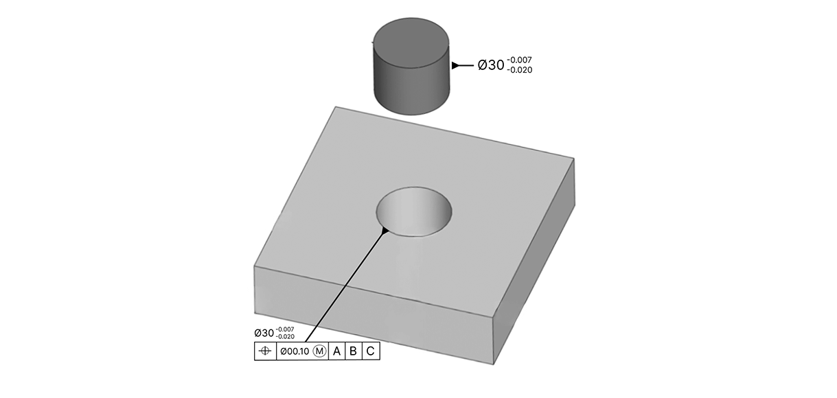
Maximum Material Condition (MMC)
MMC describes a feature containing the greatest volum of material within its dimensional tolerance. For an external feature like a pin, this is its largest permissible size. For an internal feature, such as a hole, it is the smallest allowable diameter.
What is the real application of MMC? Where we found the MMC callout in a feature control frame means that geometric tolerance will be applied when the feature is at its maximal material condition.
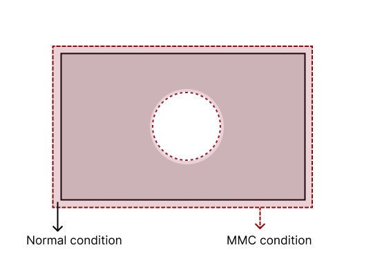
As the feature deviates from this extreme, “bonus“ tolerance is applied, simplifying inspection, recognizing manufacturing variability, and minizing unnecessary rejection of good parts.
Benefits of MMC:
- Enables bonus tolerance
- Simplifies fit and assembly verification
- Supports robust, repeatable inspection strategies
Least Material Condition (LMC)
Differently, LMC refers to the condition of the feature when it contains the smallest volume of material. For a hole, this is its largest diamater; for a pin, its smallest size.
LMC is often specified when minimum wall thickness or maximum clearance is critical, common in lightweight assemblies or structural components reliant on material integrity.
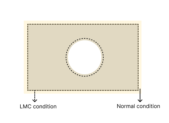
LMC used in the feature control frame indicates that the geometric tolerance is at its tightest when the feature has the least amount of material. As the feature moves away from LMC, a “bonus” tolerance is granted.
Benefits:
- Guards against insufficient strength or excessive clearance
- Given inspectors and designers greater control in critical dimensions
- Reduces risk in lightweight or boundary-sensitive features
Regardless of Features Size (RFS)
In ASME routine, RFS is applied by default in GD&T, unless MMC or LMC is specified. When RFS conditions are active, the geometric tolerance for a feature applies uniformly at any acceptable size, and no “bonus” tolerance is awarded, ensuring the tightest possible manufacturing and inspection controls.
RFS is most appropriate when both sides of a tolerance zone must be tightly maintained, or the precise geometric relationship between features is critical for function, regardless of individual feature sizes. In high-precision contexts, such as aerospace or tooling, RFS preserves integrity and ensures features perform exactly as intented at all allowable dimensions.
Benefits:
- Guarantess critical functional relationship are maintained
- Eliminated unintended variation due to size changes
- Ensures consistent precision across manufactured lots
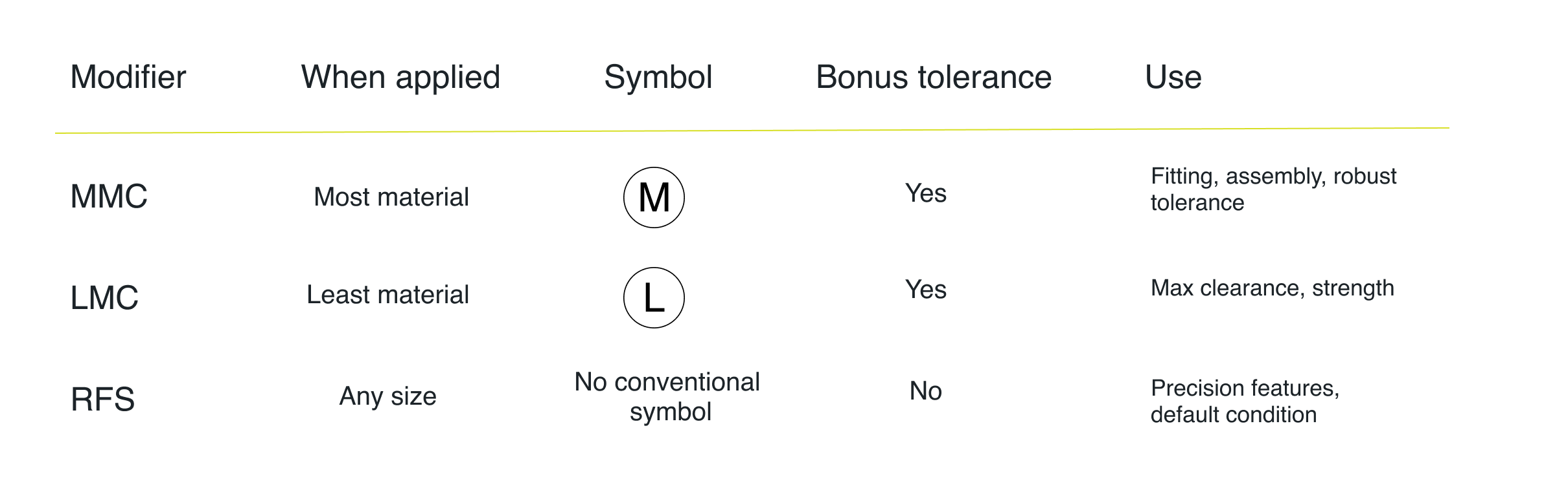
Symbols and key differences
Enjoy the TouchDMIS community.
Subscribe to our newsletter!