

Whatever your inspection workflow is with your CMM, alignment is the foundation of everything. Before a single dimension can be trusted and validated, the CMM must know exactly where and how the part sits in space. This process, known as creating a datum reference frame, defines the origin, orientation, and axes that every subsequent inspection will use.
Nonetheless, when the alignment is wrong, all results become unreliable. Size, position, and profile values can be shifted or rotated, no matter how accurate the CMM itself may be.
Hence, a stable and well-defined alignment is crucial for obtaining repeatable, traceable, and meaningful inspection data.
But, where to start from?
The most dependable way to achieve a stable and well-defined alignment is through the correct interpretation of the engineering drawing and the creation of a robust, reliable CNC alignment. A properly programmed CNC routine probes the required datums in a controlled, repeatable pattern, producing a reference frame that reflects the Designer’s intent with minimal CMM operator influence.
Although, many technicians still believe that manual alignment can provide the same results. In practice? This is rarely the case. And we will see why on this page.
Let’s examine why CNC alignment consistently outperforms manual alignment, and we will try to explain the main reason behind this difference. Understanding these principles helps metrology operators to move beyond old habits and build alignments that are both robust and fully compliant with modern GD&T requirements.
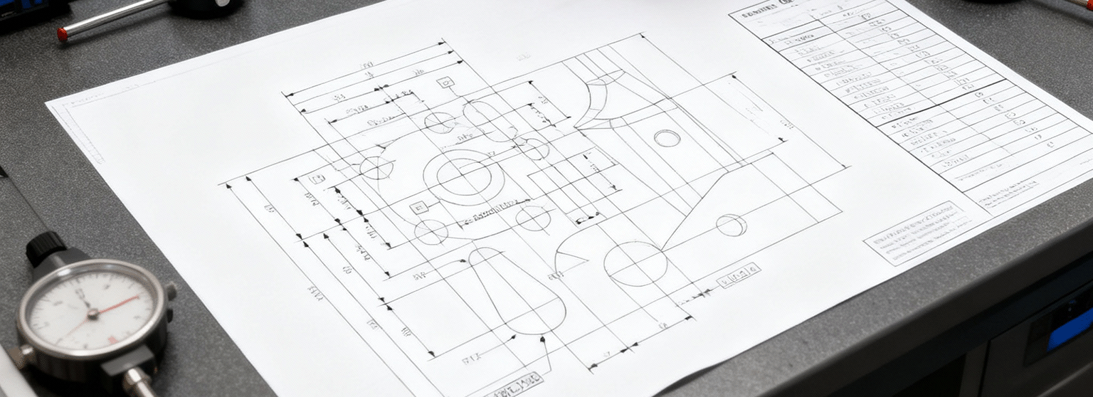
UNDERSTANDING REQUIREMENTS AND DRAWINGS
Before a probe touches the part, the most relevant question is “What is my datum?”. The answer should always come from the engineering drawing or specification document. This is because the datum reference frame is not just a convenience for inspection, but is the language that the designer uses to describe how the part functions in the assembly.
The datums define which surfaces, holes, or axes control location and orientation. They are the link between the design intent and the inspection process.
In reality, however, technical drawings are not always as precise as they should be (and we would like). Symbols may be missing, datum letters can be ambiguous, and sometimes the designer assumes a level of tribal knowledge that never makes it to the paper.
In that moment, the metrologist is tempted to rely on “heart and experience” to decide what the datums should be. Such a solution, although often efficient, is not always a best practice: the CMM exists to serve engineering, not to rewrite the design, and heart and experience must not (always) substitute the accuracy and precision!
Designers must learn to be precise in the drawing; otherwise, the operators will fill the gaps that the designer has left. The most effective and professional strategy is to challenge any unclear documentation. When the drawing leaves doubt, the first action should be to seek clarification from the designer or quality engineering team. Only a confirmed specification can guarantee that the inspection reflects the real functional requirements of the part.
Then, there are some cases, rare situations like legacy parts, urgent checks, or incomplete data, where the drawing simply cannot provide the answer in time. Here, an experienced metrologist can study the component, examine its functional interface, and propose a provisional datum scheme that respects the designer’s intent. But carefully, this until the proper documentation is available!
So, as we have seen so far, datums are fundamental in the daily metrology workflow. They must be identified on the drawing, confirmed in the specification, and treated as the Holy Grail of the alignment.
When reading a drawing, operators must look carefully for datum feature symbols placed on the feature. Following the feature control frames that reference these letters is fundamental to understanding which surfaces or axes control orientation and location. The primary, secondary, and tertiary datums define which degrees of freedom each datum locks.
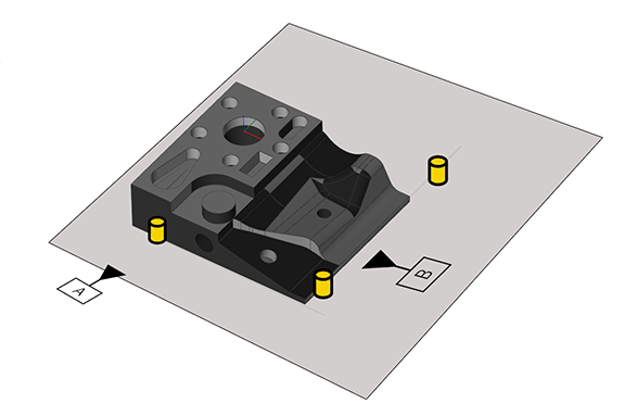
Thus, a strong datum strategy begins on the designer’s desk, but careful reading of these symbols ensures that the CMM interprets the drawing exactly as intended.
CNC ALIGNMENT VS MANUAL ALIGNMENT
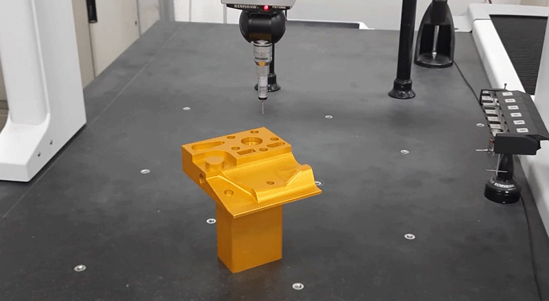
Manual alignment is generally considered the most direct and indistinctive approach. The operator manually drives the machine, selects the surfaces, and takes the points needed to define the coordinate system.
Given that alignment depends on human operation, repeatability is limited. Two operators may choose different points, or even the same operator may vary from one shift to the next. For this reason, manual alignment should be seen as a preliminary step, useful to locate the part with a sensible level of accuracy so that a true CNC alignment can be created in a second stage. The goal of this first manual setup is to position the complement well enough for the programmed routine to provide the proper datums and establish the final specification-compliant coordinate system.
Once the second stage, the CNC alignment is validated, it becomes the reference for all repeatable and traceable inspections. We must remember that CMM has no idea where the part is until the operator tells it. Unless a repeatable, pre-qualified fixture is used, the machine needs an initial reference to access the points required for the CNC routine.
This is the only real reason why manual alignments are accepted and continue to exist: to give the machine enough information to reach the features that will be measured in the final CNC alignment.
BENEFITS OF CNC ALIGNMENT
If you use a scanning probe (SP25/SP80), scan the datum surfaces whenever possible and apply proper filtering to eliminate noise while preserving form and orientation.
Instead, if you use a touch-trigger (PH10 with TP20/TP200), distribute the points widely across the surface to capture any local form error and avoid biases.
Last, in case you use a 5-axis system (PH20 or REVO), take advantage of the speed and capture many points in a short time to strengthen the mathematical fit.
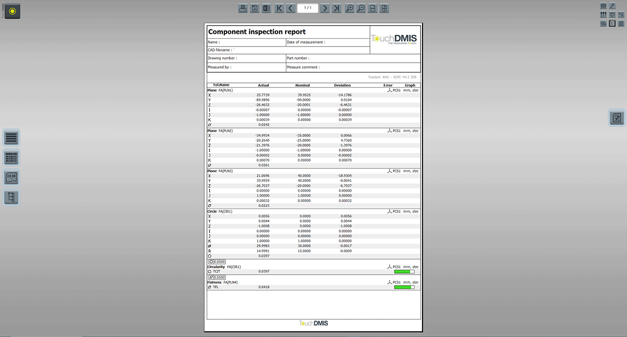
Another good practice is to include the datum features’ results in the inspection report. Including the actual deviations of the primary, secondary, and tertiary datums gives immediate confirmation that the alignment process is correct. When the report clearly proves that these datums meet their requirements, the entire inspection workflow gains credibility, and the inspection results can be trusted.
BEWARE OF FALSE FRIENDS: CIRCLES
Circles are everywhere in mechanical drawings. They appear as holes, bosses, and patterns, and for many operators, they feel like the most natural choice for an alignment feature. But in CMM inspection, a circle can be a false friend when used as a datum. A 2-D circle defines only size and location in a single plane, but it gives no control over the axis orientation that a stable reference frame requires.
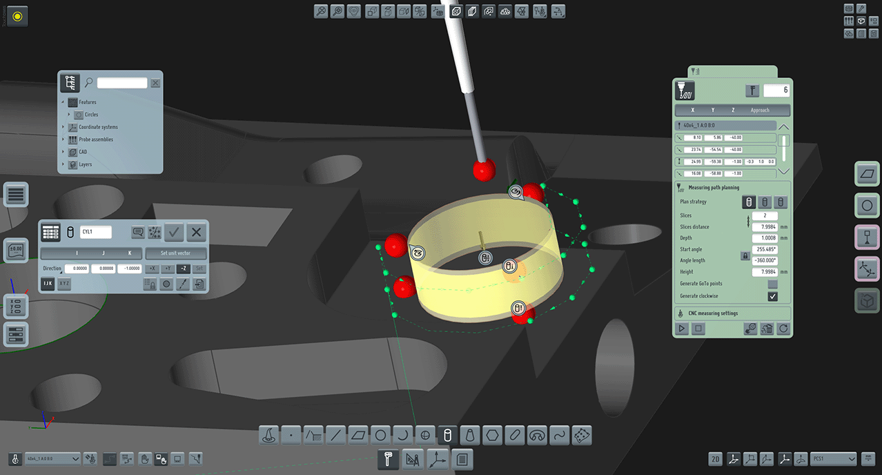
When a drawing calls out a circular frame as a datum, the best practice is to treat and measure it as a cylinder, not just as a flat circle. A cylinder provides the three-dimensional axis needed to lock rotation and tilt, ensuring that the CMM builds a datum reference that truly represents the functional behavior of the part. This is especially important for holes that guide pins, shafts, or fasteners, where any angular error directly affects the assembly.
It is common practice to define the axis of a cylinder by measuring several circular sections at different heights and then calculating a line through those centers. Although this may look like a good strategy, it is actually another false friend. A true 3-D cylinder is calculated by fitting all measured points around the full depth of the hole or boss. Its central axis comes from the entire surface, capturing any tilt or form error along the feature’s length.
By contrast, a line derived from separated 2-D circles represents only the local centers at those specific heights. But here lies the trap: the projection plane of each circle is uncertain because the underlying cylinder form error is still unknown while you are in the actual process of measuring it.
Some operators might argue that the resulting error is probably minor, but best practice cannot depend on the hope that the part has minimal error! A datum requires the most robust method available, and that means a full 3-D cylinder fit. Therefore, circles may look friendly on paper, but a metrologist who understands function will always think in cylinders and full 3D, not just 2D outlines.
WRAPPING IT ALL UP
From the first probe touch to the final inspection report, a solid datum strategy is what turns raw points into trustworthy results. At first, it may sound complex (alignment is the hardest part to learn for every operator), but once we understand its logic, datuming is not intricate at all. It’s the connection between the designer (and manufacturer) intent and the real-world inspection (and its final product).
In TouchDMIS, we have transformed the alignment operation into a fast, reliable, and easy-to-use process. Every feature is designed to help you apply the best practices effortlessly, whether you’re creating a quick manual pre-alignment or programming a full CNC routine.
Once we have inspected the part and understood the datums scheme, you can easily pick up features from the interface, select the primary, secondary, and tertiary datum, and complete the operation with a simple click or tap!
Thus, a friendly user interface and easy programming experience of TouchDMIS allow you to worry only about the interpretation of the engineering drawing.
Enjoy the TouchDMIS community.
Subscribe to our newsletter!