

Geometric Dimensioning and Tolerancing (GD&T) is a precise symbolic language used in engineering drawing (and metrology) to define and control parts’ shape, orientation, location, and profile.
Unlike conventional dimensioning, which relies only on linear and angular tolerances, GD&T provides a structured framework that ensures parts meet functional requirements while allowing for manufacturing flexibility.
The system is based on a set of standardized symbols and rules that define allowable variations in geometry, making it easier for designers, manufacturers, and quality inspectors to communicate and interpret specifications in the right way.
By using a feature-based approach and a well-defined datum system, GD&T minimizes ambiguity, reduces errors, and ensures consistency in the production and inspection of components.
BENEFITS OF GD&T
GD&T offers several advantages over traditional tolerancing methods, making it an essential tool in modern manufacturing and quality control.
One of its primary benefits is improved communication, as it provides a universally understood language that eliminates misinterpretation of design intent.
Additionally, GD&T enhances functional fit by ensuring that tolerances are applied based on the actual function of a part, rather than arbitrary limits, leading to better assembly and performance.
From a manufacturing perspective, GD&T increases efficiency by allowing for more flexible tolerances where possible, reducing costs while maintaining quality.
In quality control, GD&T simplifies inspection processes by defining clear measurement criteria, ensuring repeatability and reliability.
Moreover, it facilitates the interchangeability of parts by standardizing geometric constraints, making it easier to produce components that consistently meet design specifications.
BASICS OF GD&T
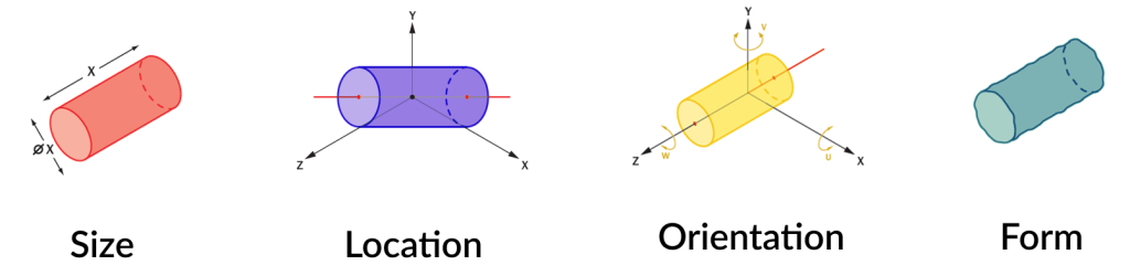
At its core, GD&T controls four fundamental aspects of a feature, often referred to as SLOF: Size, Location, Orientation, and Form. Let’s see:
- Size refers to the allowable variation in the dimensions of a feature, such as the diameter of a hole or the width of a slot
- Location defines the permissible position of a feature relative to a datum or another feature, ensuring proper alignment and assembly
- Orientation controls the angular relationship of features, ensuring they remain parallel, perpendicular, or at a specified angle to a datum
- Form dictates the shape accuracy of a feaute, sush as its flatness, straightness, circularity, or cylindricity, independent of its location or orientation.
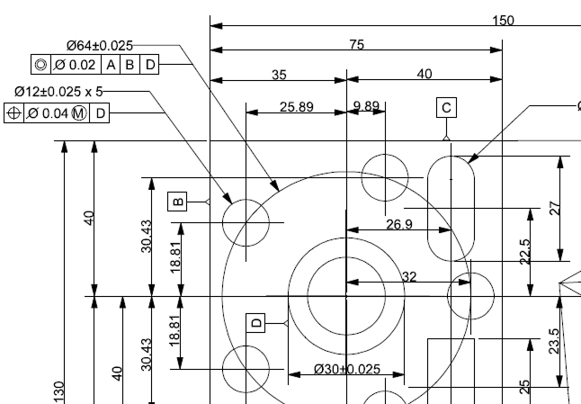
To specify these controls, GD&T uses feature control frames, a rectangular box that includes geometrical characteristic symbols, tolerance values, datum references, and material condition modifiers (MMC, LMC).
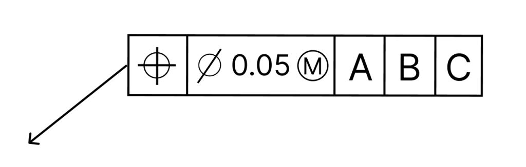
Maximum Material Condition (MMC) and Least Material Condition (LMC) are modifiers used in GD&T to optmize tolerancing based on a feature’s material state.
- MMC refers to the condition where a feature contains the maximum material within its tolerance limits (“the smallest hole or the largest pin”). This ensures that part maintain functionality, especially in assembly, where clearance and interference are critical.
- LMC represents the condition whit the least amount of material (“the largest hole or the smallest pin”), often is used in applications where wall thickness or minumum strength is a concern.
These modifiers allow for bonus tolerance, meaning the allowable geometric variation increases as the feature departs from its material limit, improving manufacturability without compromising functionality.
GD&T Tolerances
The GD&T tolerances are standardized under ASME Y14.5 and ISO GPS. Here is a breakdown:
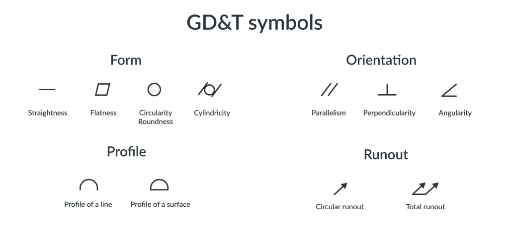
FORM TOLERANCES (Control the shape of a feature)
- Straightness: Ensures a feature is straight within a specified tolerance
- Flatness: Controls the flatness of a surface or plane
- Circularity / Roundness: Ensures a circular is round within a tolerance
- Cylindricity: Controls roundness and straightness along a cylinder’s length
ORIENTATION TOLERANCES (Control the angular relationship between features)
- Parallelism: Ensures a feature is parallel to a reference
- Perpendicularity: Ensures a feature is at 90° to a reference
- Angularity: Controls the angle between a feature and a reference
LOCATION TOLERANCES (Control the exact position of features)
- Position: Defines the allowable variation in the location of a feature
- Concentricity: Ensures the central axes of two or more features are aligned
- Symmetry: Controls the symmetrical relationship between two features
PROFILE TOLERANCE (Control the shape of a feature in 2D or 3D)
- Profile of a line: Controls the shape along a surface in a single cross-section
- Profile of a surface: Controls the entire surface’s shape, ensuring it conforms to a 3D tolernace zone
RUNOUT TOLERANCES (Control feature movement relative to a datum)
- Circular runout: Ensures a feature’s roundness to a datum whe rotated
- Total runout: Controls a feature’s entire surface movement relative to a datum
ASME Y14.5 sets also the standard for symbols specifying geometrical characteristics and other dimensional requirements:
Enjoy the TouchDMIS community.
Subscribe to our newsletter!